Balancing
The purpose of balancing is: To determine the phase (direction) and amplitude (magnitude) of the unbalance forces and eliminate them with corrective action.
The corrective action may include applying a correction mass or drilling away the excess weight 180° opposite the original imbalance.
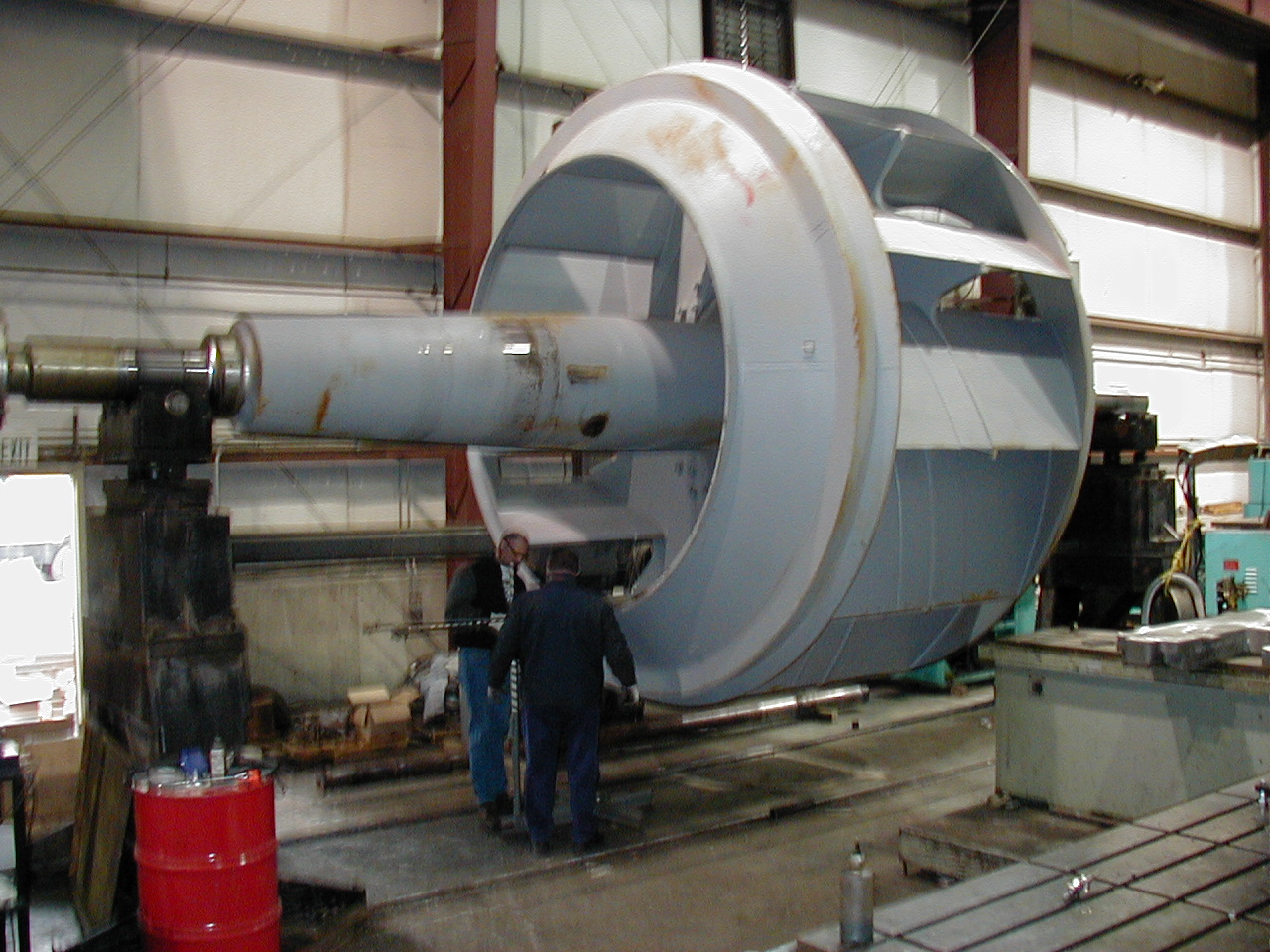
Static imbalance will mainly occur with narrow rotors, where there is no axial motion. This type of imbalance is corrected in a single radial plane of the rotor, and as close as possible to the plane of the center of gravity. Therefore, this method of balancing is also called single plane balancing. Typical rotors that often require single plane balancing in mounted condition are:
- fans and air separators
- flywheels, pulleys, clutches
- gears, etc.
- electric motors and generators fixtures
- paper machine rolls
- centrifuge drums and decanter rotors
- compressor rotors, etc.
Balancing an implement can be performed in two ways:
- without a phase angle measurement
- with a phase angle measurement.
Balancing using a phase angle measurement is done as follows:
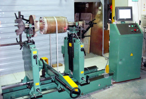
For this, one needs a vibration meter that gives information about amplitude and frequency. Here the amplitude serves as a measure of the force produced by the imbalance. In addition, a phase meter is needed that provides information about the required phase angle between the instantaneous position of the axis and the position of the imbalance force in the tool. The vibration of the imbalance is measured by the transducer, which is mounted on a bearing housing. The vibration signal passes through a filter tuned to the speed of the machine. (Only the frequency of imbalance is now measured). This information goes to the vibration meter and to the phase meter.
A piece of reflective material is glued to the shaft that records its position. The optical pulse pickup is placed at this axis and emits a pulse when a piece of reflective material passes the optical eye of the pulse pickup. The pulse pickup passes this pulse to the phase meter. The difference in time between the pulse and the highest peak of the vibration signal is expressed by the meter in degrees. By drawing the values found in a vector diagram and applying a formula to it, it is possible to determine the position and mass of the correction weight.
There will be different variations of balancing with a phase angle measurement, however, they will be broadly similar to the concept described above. Because people in practice want to be able to perform a balancing job correctly and quickly, equipment with a user-friendly balancing program is increasingly offered on the market. These programs will ensure that the correct values of correction weights and their positions are quickly indicated. All this is accomplished with the help of a built-in calculation program, which minimizes the operations to be performed.
Balancing in practice
Single plane balancing:
Before balancing, a piece of reflector material must be glued to the spinning tool. The location of the vibration meter will also need to be determined. In general, the vibration transducer is positioned horizontally at the bearing that indicates the highest vibration amplitude.
- First, the initial imbalance is determined, by measuring the vibration magnitude and phase angle during an initial run (point A: 7.8 mm/s RMS, 50°).
- Then a trial weight (which is calculated using rotor data) is mounted on the implement at 0°. Now by making another run (the so-called test run), again the vibration magnitude and phase angle are determined (point B:6.60 m/s RMS, 160°)
- Now drawing a line between these two points (A and B) creates the trial vector. Using the length of the trial vector and the mass of the trial weight, the proper correction weight can be calculated. To get proper balance point A must be moved to point C. This can be done in this case by rotating the test vector at an angle of 32° the calculated correction weight is mounted the implement will be balanced again.
- Finally, a control run is made (the so-called check run), to see how far the vibration level has dropped. When this level is within established tolerances, balancing is complete.
Two plane balancing:
Before balancing can be done, a piece of reflective material will also have to be glued to the spinning tool. The locations of the vibration transducers will also have to be determined again. In general, the vibration transducers are positioned horizontally, on both bearings (2 planes!).
- First, the initial unbalance for both surfaces is determined, by measuring the vibration magnitude and phase angle during a first run (one now gets 2 diagrams). The principle is similar to that of single plane balancing.
- Then a test weight (which is calculated from rotor data) is mounted on the side of plane 1 at 0°(equal to reflection material) on the implement. By now making another run (the so-called test run), the vibration magnitude and phase angle are again determined for both planes.
- The trial weight is then moved to the side of plane 2, and also mounted on the implement again at 0°. Again, a test run is made, determining the vibration magnitude and phase angle of the two planes.
- The trial weight is now removed in its entirety, after which the computer calculates the required correction mass and phase angle per plane. This calculation is much more complicated than that of single plane balancing, so it is a good thing that the computer calculates it for us.
- Finally, a control run is made (the so-called check run), to see how far the vibration level per plane has dropped. When this level is within established tolerances, two-level balancing is complete.